In this post I want to show how to put together a guitar pedal if you have basic soldering skills and basic knowledge of electronics. With this I mean recognising different components, knowing what’s the correct orientation of diodes and electrolytic capacitors and being able to read a basic circuit just in case there is some troubleshooting to do.
To start with I will show how to put together a pedal from a Kit. There are a lot sites out there that sell kit will all components and also offer a pre-drilled enclosure. Probably the most famous is BYOC, but as I said there are quite a few that not only offer original designs, but also clones of popular pedals (like in this case).
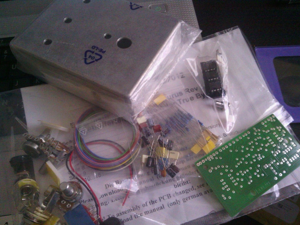
This is what I received in the post a few days after ordering from a German website.
As you can see all components are separate, and before you start I definitely advice to read all instructions! In this case I found out that you could follow two separate sets of instructions, one for true bypass and one for a buffered version. All instructions were in German which did not help…!
A trick I have learnt to speed up the process is to identify all resistors and capacitors by taping them on the ‘bill of materials’ page like in the picture below.
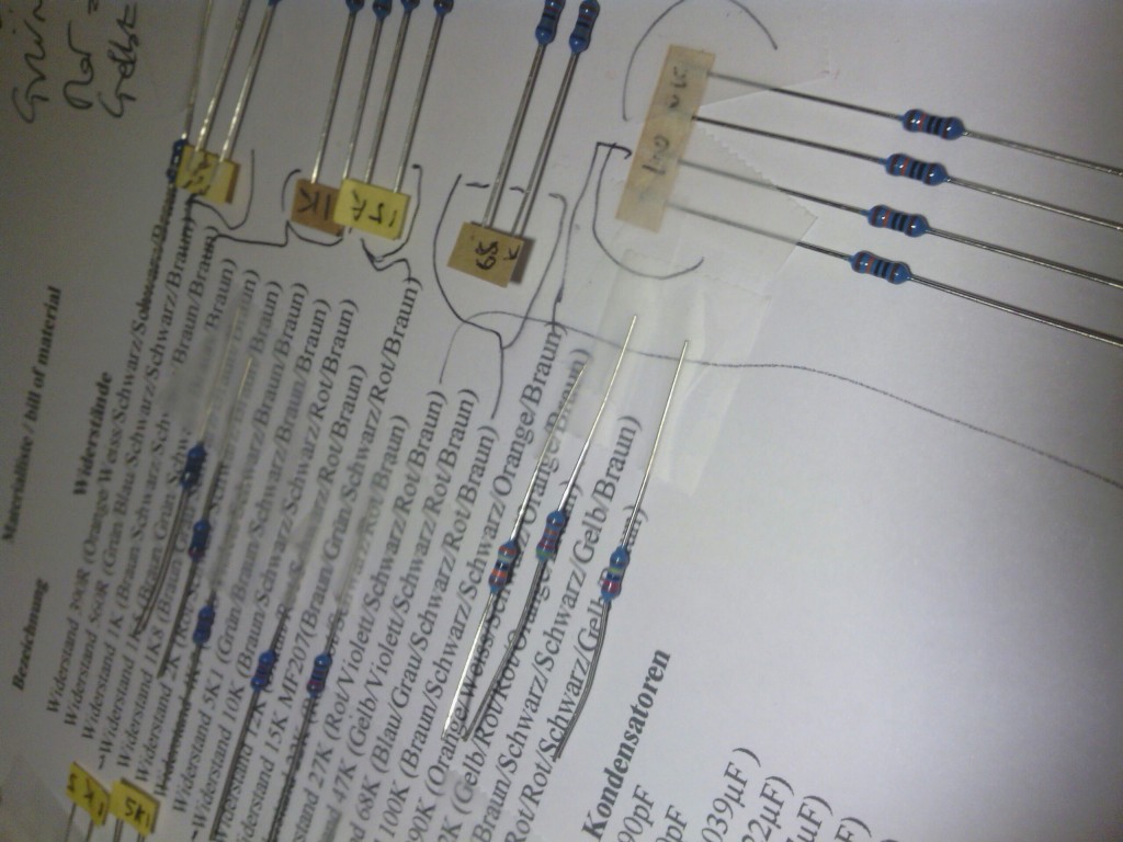
This makes things much easier when you will start populating (soldering components onto) the PCB.
After that I started to look into soldering components to the PCB, I decided to go for the buffered version, as this particular overdrive had a famously great sounding buffer section. I am not a fan of buffers, but I was curious to test it out. It can always be converted to true bypass with some small modifications.
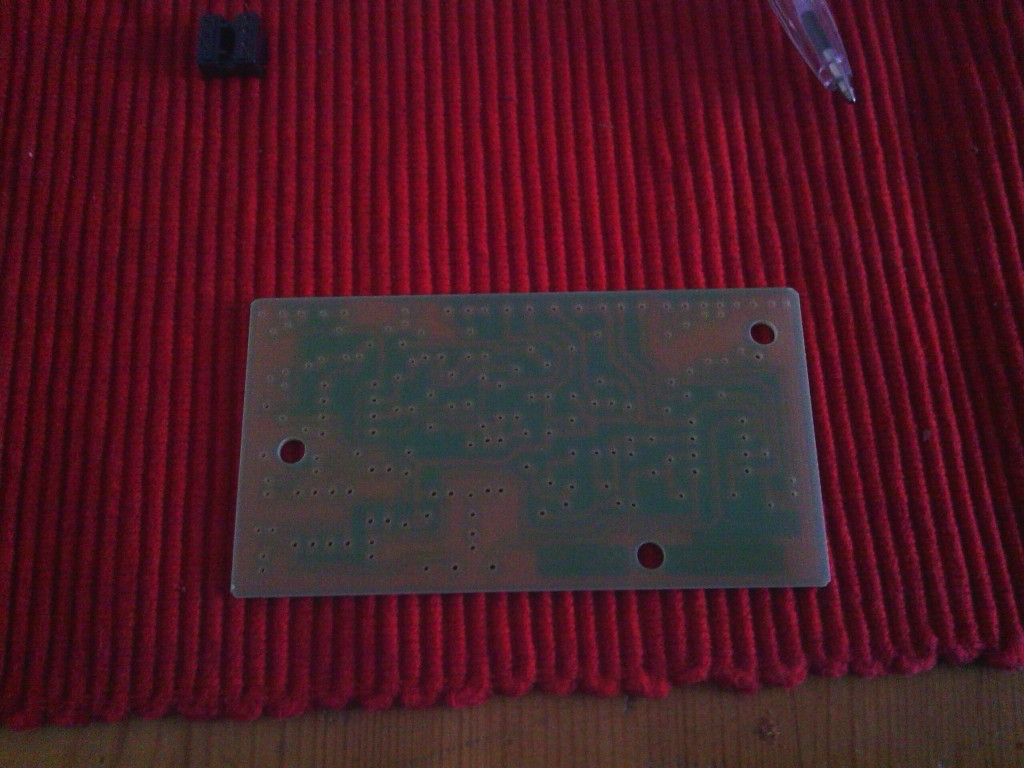
The layout is intended to match the ‘plain’ side of the PBC facing you, the one without the exposed metal circles, to be clear.
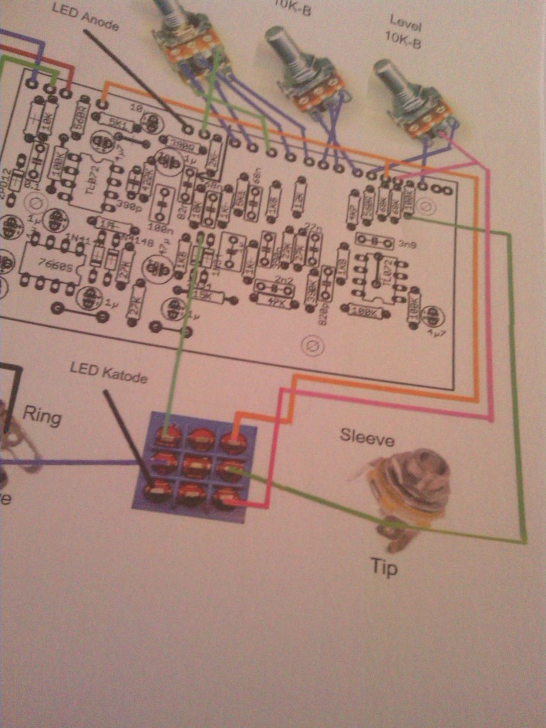
So this is what should be in front of you before you start soldering.
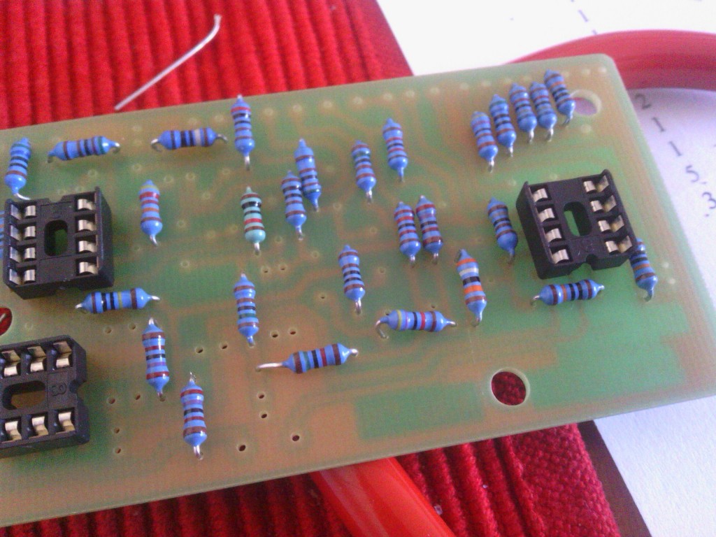
Next I started soldering all resistors onto the board and the IC sockets.
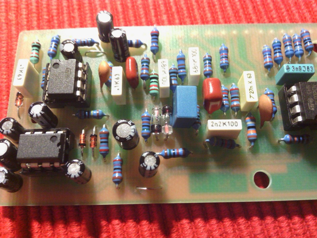
Following that all Diodes and Elect Capacitors. Make sure you pay attention to the orientation of these two types of components. Diodes have a black band that needs to be on the correct side and Capacitor have the negative side marked usually by a different coloured band. This will all be marked on the PCB layout or on in the circuit.
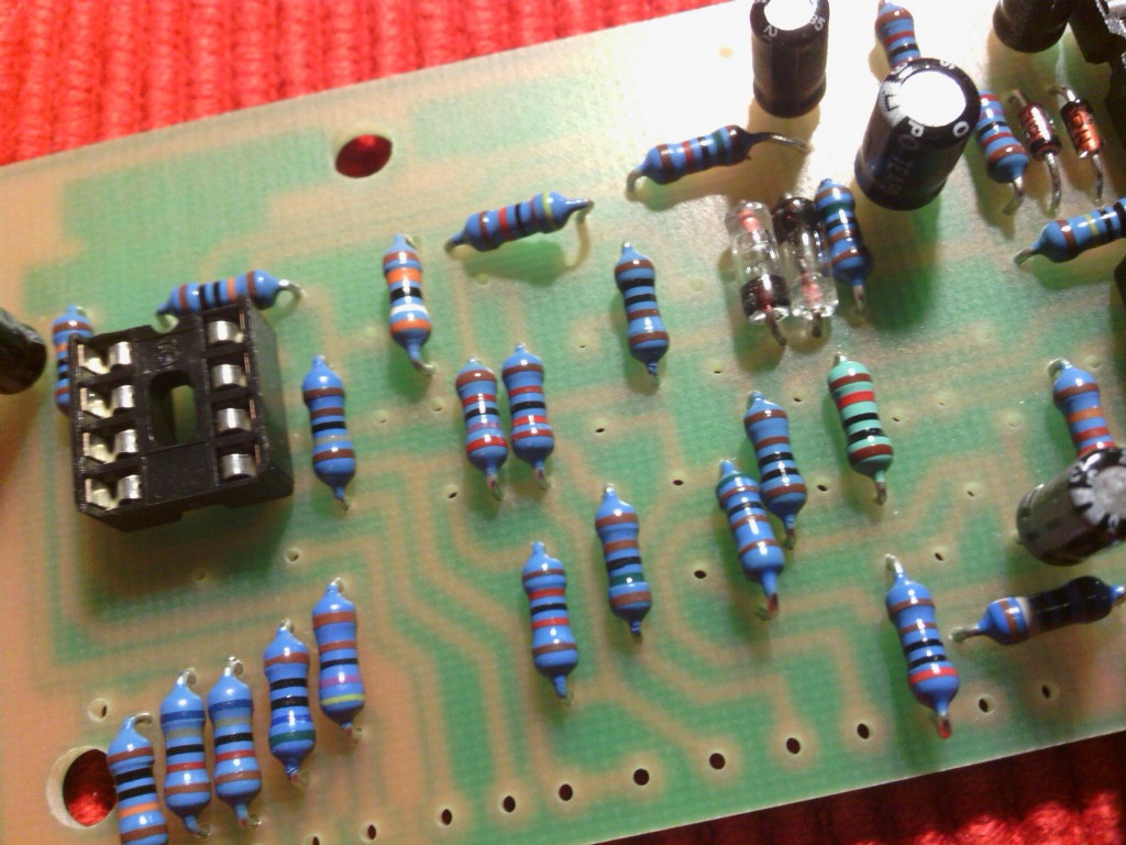
Next you will solder all remaining capacitors and slot the IC’s onto the sockets.
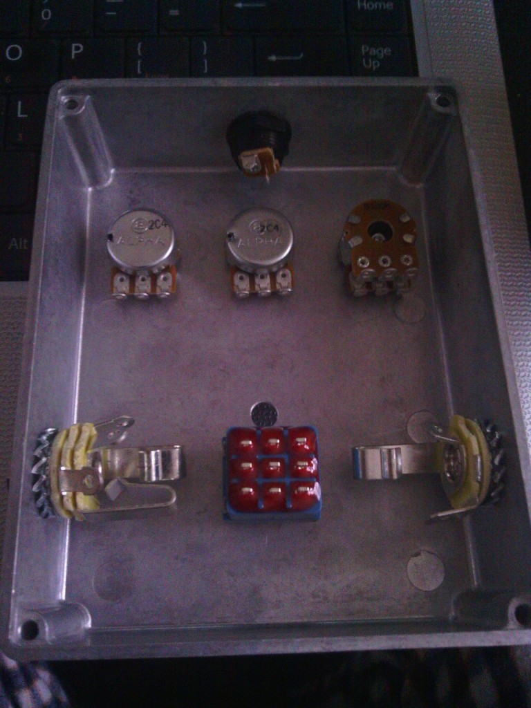
Almost there! Next you want to screw the potentiometers, jacks, foot switch, led holder and power socket on the enclosure. Sometimes (like I found out later in this case) it is better to wait to fit the potentiometers to the box, as it might make them easier to solder to the PCB.
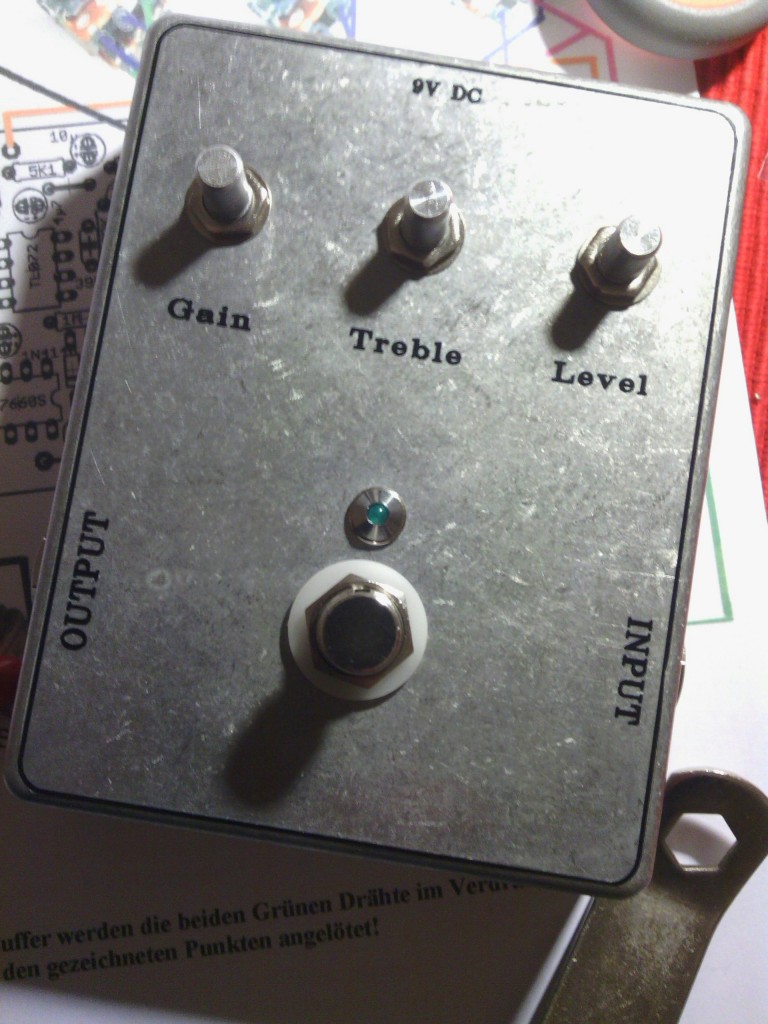
Before screwing all things onto the box I had applied the decals onto the front of the enclosure, I did this by using waterproof inkjet printable adhesive vinyl. It is an easy option and I found it lasts quite a bit without having to powder coat the boxes or having to spray paint them. Also you can use a regular printer which makes for potentially very creative artwork. I opted for a very basic and clear layout, but if this pedal makes it to my board, I will make it more interesting to look at!
You can now start soldering the leads to the input output and power section. This will all be shown in the main layout on the instructions.
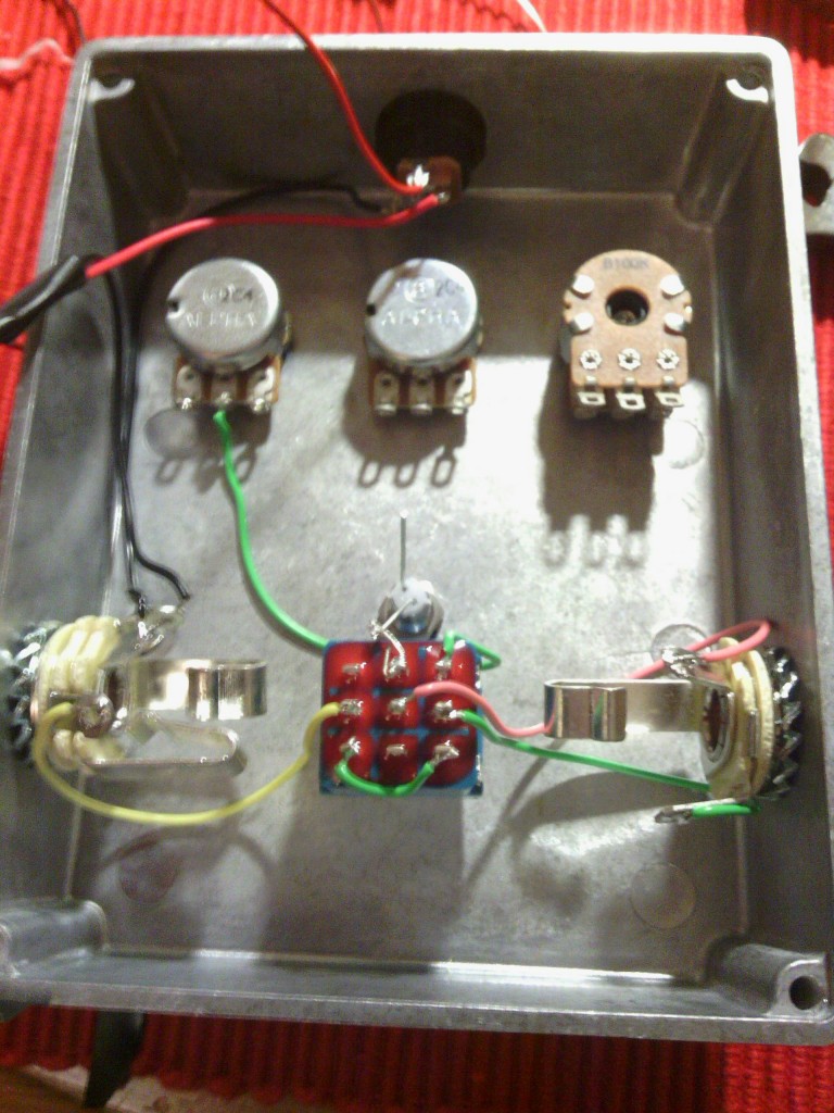
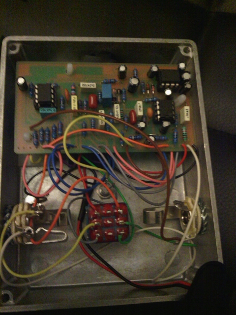
At this point I will connect the PCB to the potentiometers and in/out/power connections.
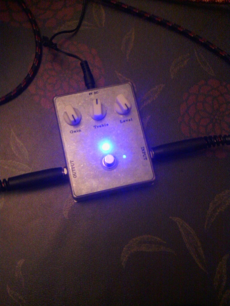
I will tidy up all the wires later, I just want to find out if it all works OK or it needs some troubleshooting. Luckily it all work fine, and it sounds great. Below the picture of the finished product in action!
